MODBUS Protocol
Serial Communications
Any transmission sending one bit at a time can be called serial communication. It’s one of the principle of communication, not specifying any protocol. The speed ranges from few bps to Gbps. Examples includes: CAN, RS-485/232, IIC
Protocol Stack and OSI Model
The intact Open System Interconnection model contains 7 layers. The Internet is a good example.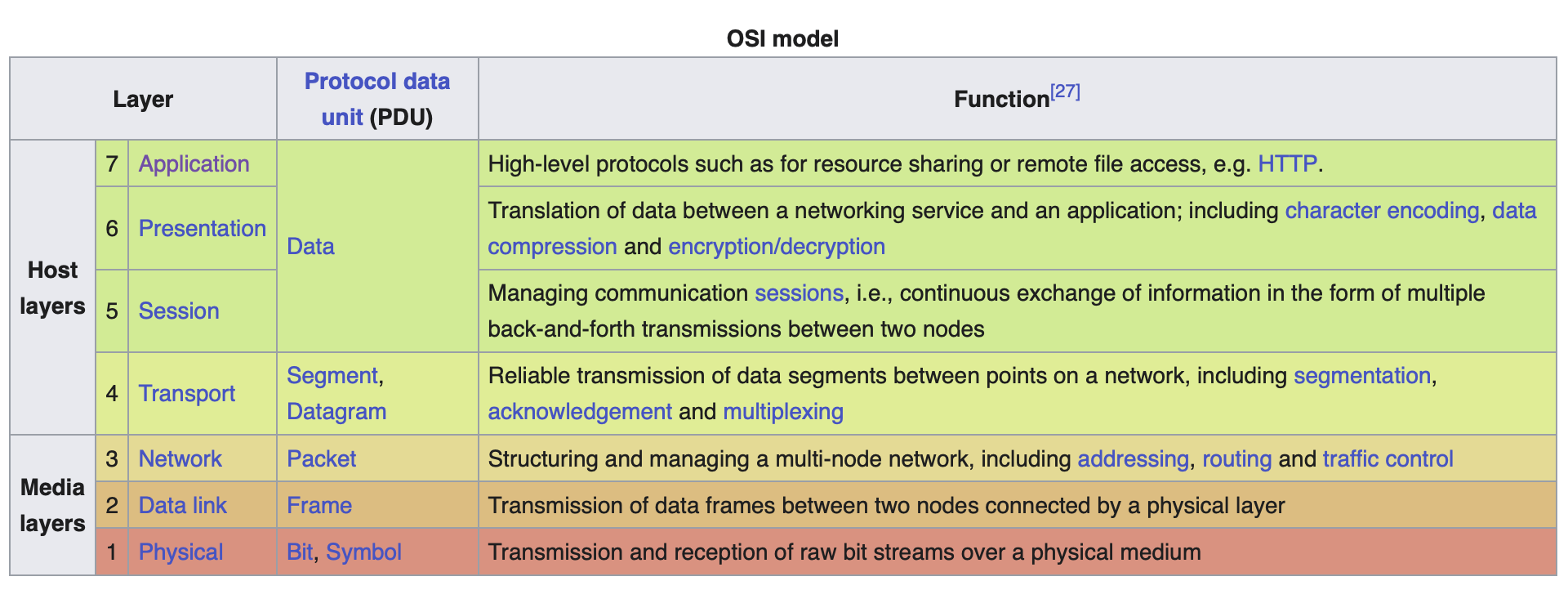
It’s notable that not all 7 layers are required for any protocol. Also, the different methods in the same layer can easily be replaced and altered.
RS-485 and RS-232
They are not a so-called communication protocol, they are more like the physical layer.
They just refer to an electrical interface, defining signal levels, speed and etc.
RS485
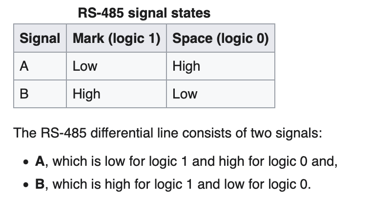
high level: +5v
RS232
TTL voltage level to 232 voltage level
high level : +12v
low level : -12v
UART
In OSI level terms, UART lives on layer 2, the Data link layer
A UART contains those following components:
- a clock generator, usually a multiple of the bit rate to allow sampling in the middle of a bit period
- input and output shift registers, along with the transmit/receive or FIFO buffers
- transmit/receive control
- read/write control logic
MODBUS
MODBUS is a protocol in the application layer. There are currently 3 implementations:
- TCP/IP over Ethernet
- Serial Bus like RS-232/RS-485
- MODBUS PLUS, a high speed token passing network
Here, we emphasize the MODBUS over Serial Line protocol.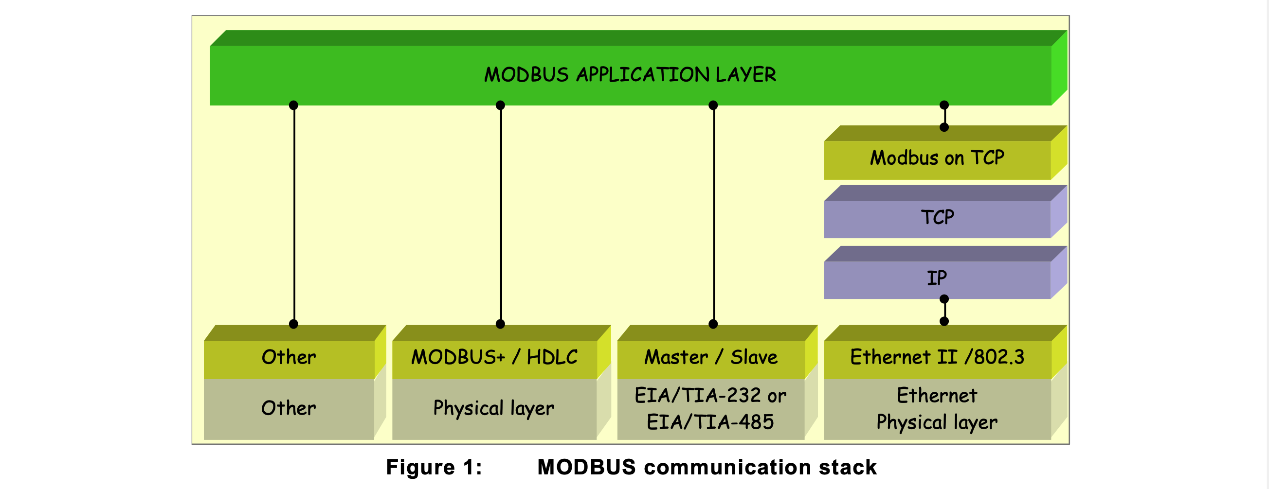
Data Blocks
The MODBUS protocol defines a simple protocol data unit (PDU) independent of the
underlying communication layers. The mapping of MODBUS protocol on specific buses or
network can introduce some additional fields on the application data unit (ADU).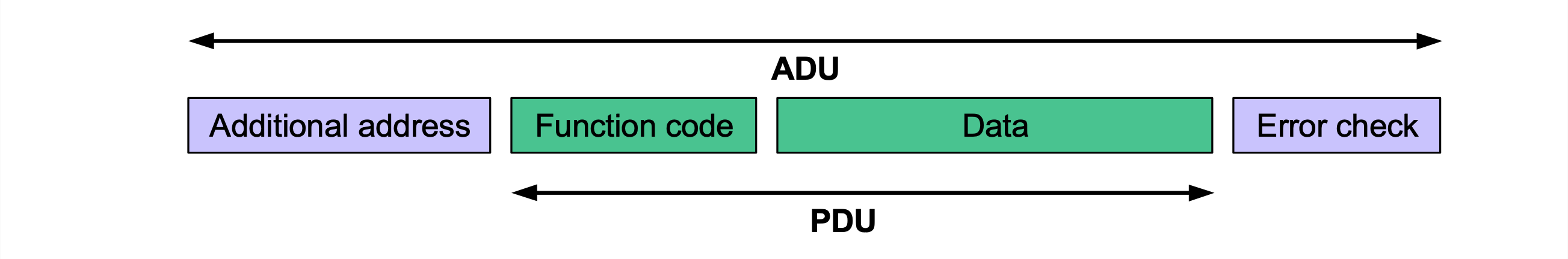
PDU (protocol data unit)

= Function code + function data
253 bytes max
Function code:
1byte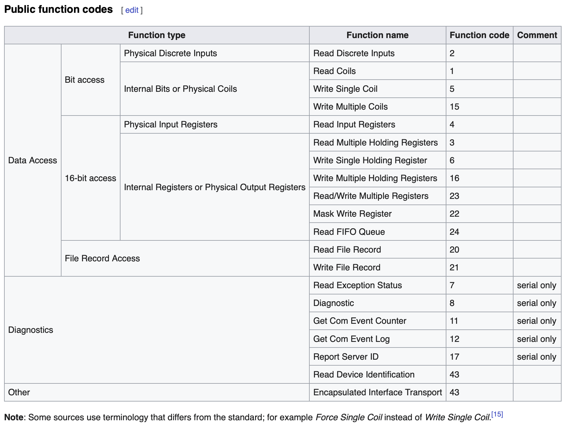
Data: address
2bytes+ data
ADU(application data unit)
= Additional address + PDU + error check
256bytes max(RS232/RS485) / 260bytes max(TCP)
Modbus Serial Line PDU
= Address + PDU + CRC (or LRC)
and PDU = Function code + data
- Address is slave address
- maximum 247 (from 1-247)slaves
- 1 master, sending broadcast with address 0 (it’s not master’s address)
- slaves must accept broadcast exchanges but not respond
- PDU is defined identically to the PDU of Modbus Application protocol
- The Error check field with CRC/LRC: The error check methods depend on the protocol versions of the MODBUS over Serial Line, whether it is Modbus RTU or Modbus ASCII.
Modbus RTU
RTU = Remote Terminal Unit
The most common implementation available for Modbus
Modbus RTU message must be transmitted continuously without inter-character hesitations
Modbus message:
- 1 start bit
- 8 bit data, LSB bit is first sent (actual payload)
- 1 bit parity
- 1 stop bit
Modbus RTU frame:
- 1 byte slave address
- 1 byte function code
- 0-252 bytes data
- 2 bytes CRC
- CRC-16-MODBUS
- $x^{16}+x^{15}+x^2+1$
The reality of the situation in more modern implementations is far from simple. Bracketing the packet is a pair of silent times—that is, periods where there is no communication on the bus. For a baud rate of 9,600, this rate is around 4 ms. The standard defines a minimum silence length, regardless of baud rate, of just under 2 ms.
Modbus ASCII
Use of ASCII characters for protocol communication
Modbus ASCII frame:
- 1 byte start with
:(0x3A) - 2 bytes address
- 2 bytes function
- 2*n bytes data
- 2 bytes LRC
- 2 bytes end with
CR/LF(0x0D + 0x0A)
Transaction
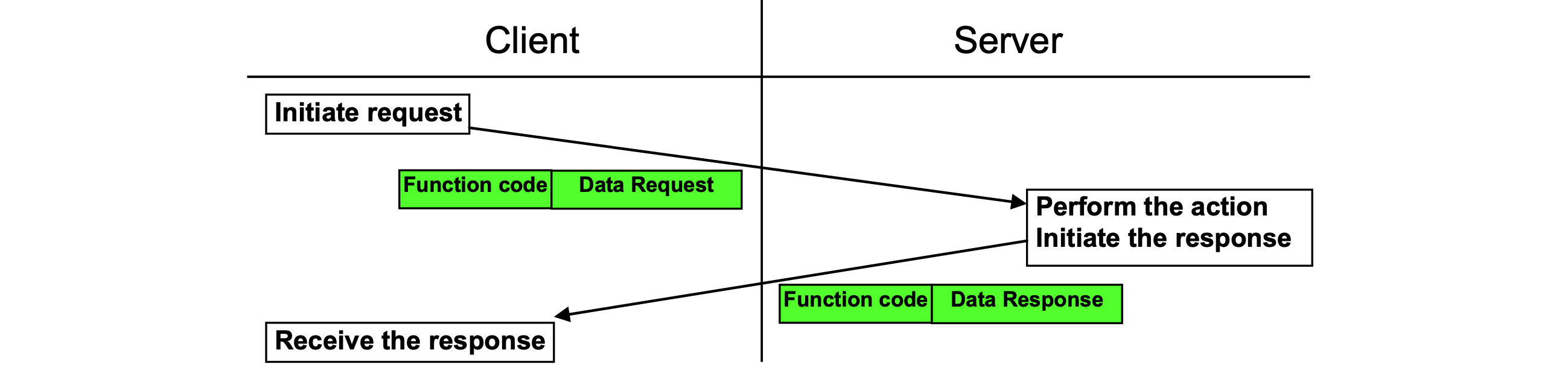
Error free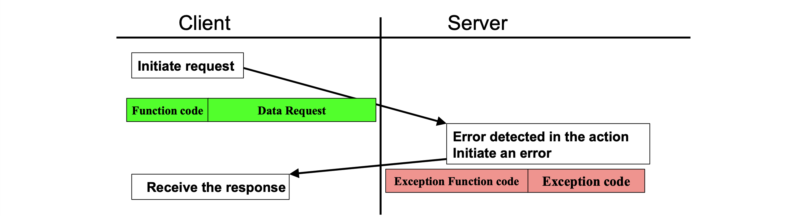
Exception response
Instance
Server -> Client: 01 04 00 54 00 0C B0 97
- Address:
01 - PDU:
04 00 54 00 0C- Function code:
04: 读输入寄存器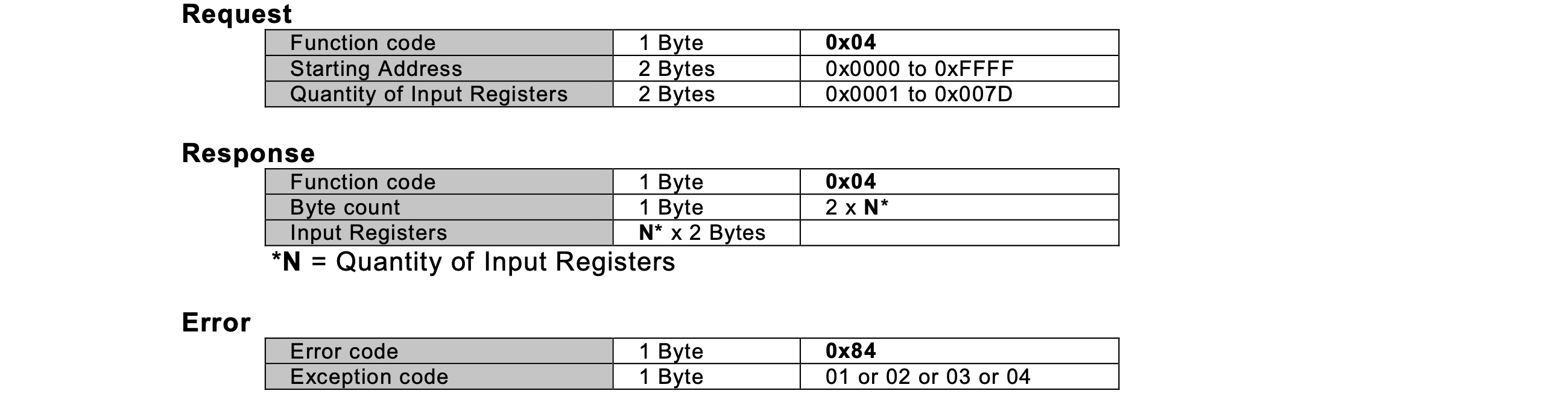
- Start address:
0x0054 - Quality of input registers:
0x000c= 12 registers
- Function code:
- CRC:
B0 97
Client -> Server: 01 04 4E Fx_L Fx_H Fy_L Fy_H Fz_L Fz_H Mx_L Mx_H My_L My_H Mz_L Mz_H Crc_L Crc_H
- Address
01 - PDU:
04 4E Fx_L Fx_H Fy_L Fy_H Fz_L Fz_H Mx_L Mx_H My_L My_H Mz_L Mz_H#ERROR - CRC:
Crc_L Crc_H